
Fiber & Outside Plant field answer
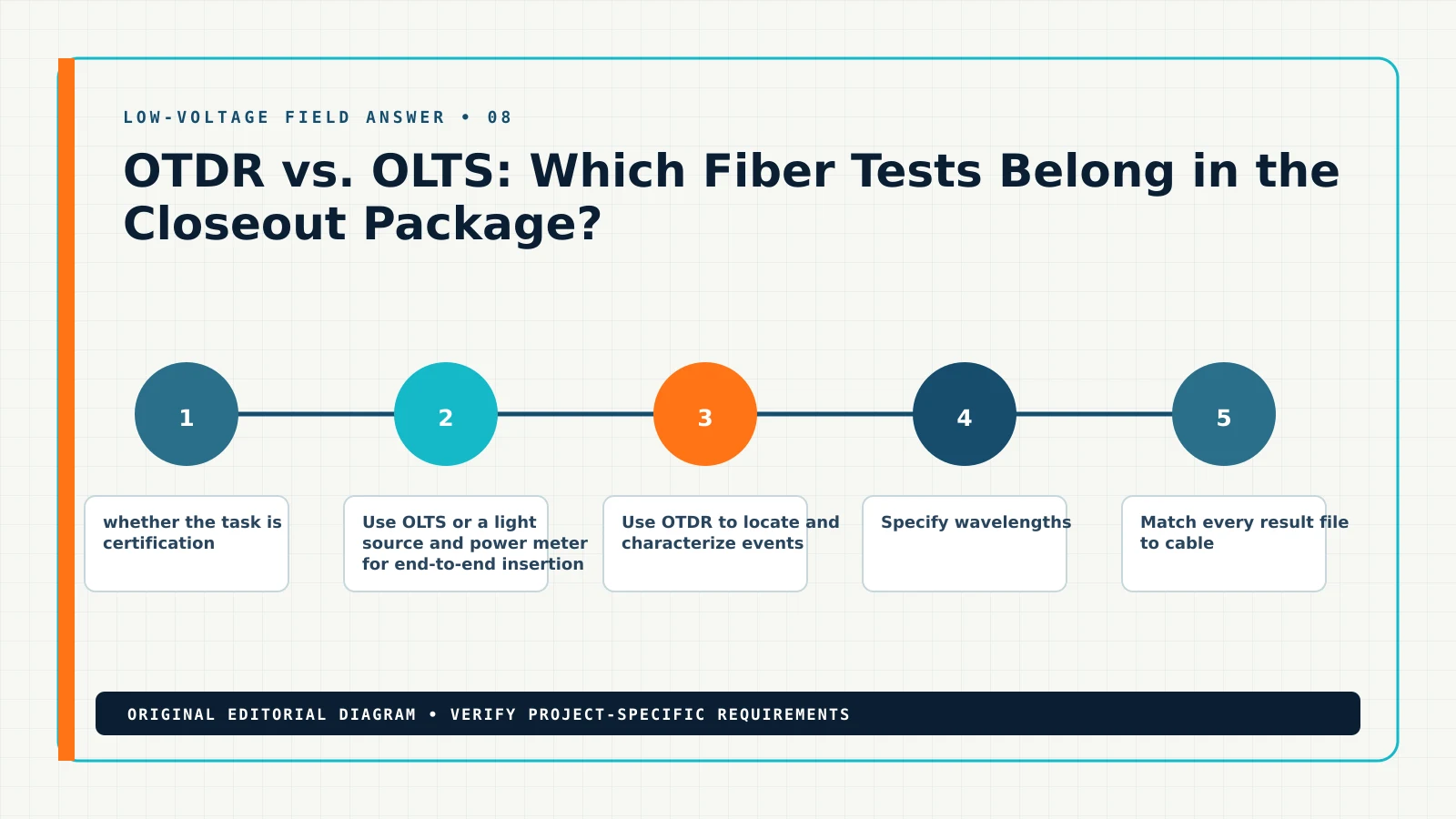
OTDR vs. OLTS: Which Fiber Tests Belong in the Closeout Package?
Choose test methods by purpose: end-to-end insertion-loss acceptance, polarity and length verification, event mapping, splice evaluation, troubleshooting, and baseline documentation. This contractor-focused guide answers the search directly, shows the project records that should carry the decision, and explains how to move from preliminary intent to a traceable proposal and field handoff.
OTDR vs OLTS fiber testing: the practical answer
Choose test methods by purpose: end-to-end insertion-loss acceptance, polarity and length verification, event mapping, splice evaluation, troubleshooting, and baseline documentation. A useful answer does not begin with a product count or a decorative symbol. It begins with the outcome the customer or operator needs, the field evidence available, the system relationships that produce the outcome, and the constraints that could change the work.
Build the record so another qualified person can audit it. Every key location, endpoint, cable, pathway, port, controller, rack, power source, network service, software dependency and test should have an identity appropriate to the project. Every important value should show whether it is verified, selected, calculated, assumed, excluded or awaiting another party. That distinction prevents early planning information from becoming an accidental promise.
For fiber & outside plant, keep the focused question connected to the broader system. Coordinate routes, entrances, handholes, splice points, closures, strands, terminations, equipment, loss assumptions, testing, quantities, and restoration scope. The immediate answer may sit on one page, but it can affect schedules, diagrams, infrastructure, labor, licensing, customer responsibilities, commissioning and closeout. A professional workflow exposes those consequences before pricing is locked.
Six inputs that make the answer defensible
The table is an intake map. Replace generic phrases with project facts and cite their origin. When a fact is unavailable, use a field-verification item, allowance, alternate, prerequisite or exclusion; do not silently invent precision.
| Input | Decision to close | Primary record | Status example |
|---|---|---|---|
| OLTS | Define whether the task is certification, characterization, troubleshooting, restoration, or warranty evidence | OSP or campus route plan | manufacturer-confirmed requirement |
| OTDR | Use OLTS or a light source and power meter for end-to-end insertion loss where specified | Fiber cable and structure schedule | customer-approved choice |
| Tier 1 testing | Use OTDR to locate and characterize events, faults, bends, connectors, and splices | Strand and splice matrix | qualified calculation input |
| Tier 2 testing | Specify wavelengths, directions, reference method, launch and receive conditions, and pass/fail basis | Backbone/riser diagram | authority or design-team decision |
| launch cord | Match every result file to cable, strand, direction, route, endpoint, technician, and instrument | Loss-budget worksheet | explicit allowance or exclusion |
| reference method | Inspect endfaces, verify polarity, resolve marginal results, and preserve native plus human-readable files | Testing and restoration closeout plan | verified field condition |
The primary record is not the only record. The design succeeds when the same identity can be traced from location to schedule, relationship diagram, quantity, proposal, field change and acceptance evidence. A change to one input should produce a visible impact review rather than an unexplained revision.
Build the answer into the drawing and project record
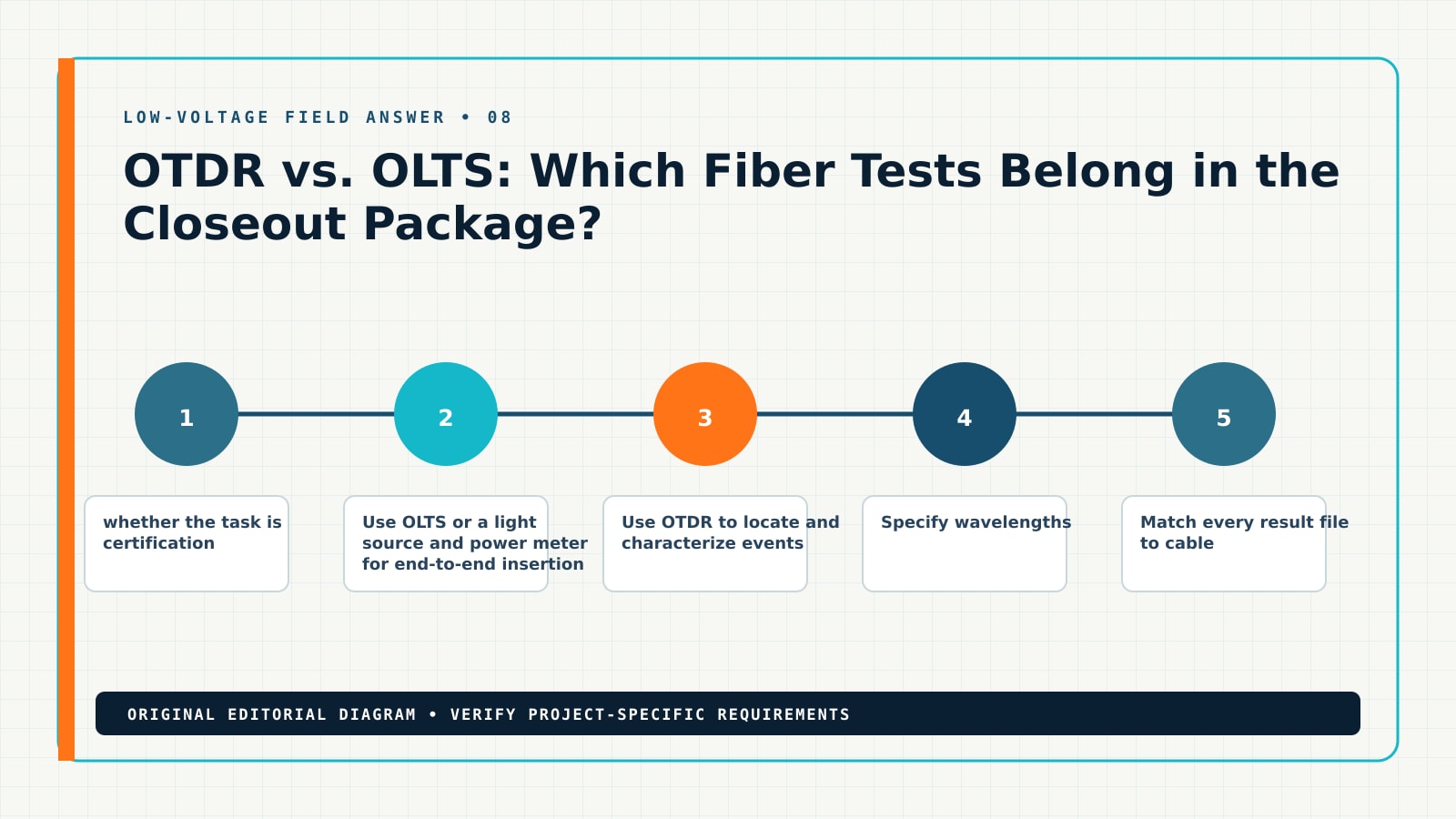
1. Baseline evidence: Define whether the task is certification, characterization, troubleshooting, restoration, or warranty evidence
Establish the basis. Start with Campus or outside-plant route segments with structure IDs, lengths, method, surface, access, and restoration notes and preserve the governing source. Record who supplied it, when it was checked, which revision it controls, and why it qualifies as a manufacturer-confirmed requirement. Separate measured facts from selections and allowances.
Make it reproducible. Put the input beside its units, route, device or endpoint identity. Cross-reference the result to Building A entrance, the applicable schedule, plan callout, quantity takeoff and scope note so another qualified person can repeat the check.
Test sensitivity and ownership. Review Property, easement, right-of-way, utility-locate, permit, traffic, environmental, railroad, and jurisdiction requirements. Identify the limit, margin and failure condition; then assign who must recheck the result if distance, quantity, equipment, topology, operating mode or project criteria change.
2. Plan and schedule: Use OLTS or a light source and power meter for end-to-end insertion loss where specified
Establish the basis. Start with Fiber cables by type, count, construction, environment, origin, destination, reserve, slack, and status and preserve the governing source. Record who supplied it, when it was checked, which revision it controls, and why it qualifies as a customer-approved choice. Separate measured facts from selections and allowances.
Make it reproducible. Put the input beside its units, route, device or endpoint identity. Cross-reference the result to HH-01 handhole, the applicable schedule, plan callout, quantity takeoff and scope note so another qualified person can repeat the check.
Test sensitivity and ownership. Review Aerial versus underground construction, pole loading, make-ready, trench/boring conditions, ducts, handholes, and restoration. Identify the limit, margin and failure condition; then assign who must recheck the result if distance, quantity, equipment, topology, operating mode or project criteria change.
3. System relationship: Use OTDR to locate and characterize events, faults, bends, connectors, and splices
Establish the basis. Start with Handholes, vaults, poles, ducts, innerduct, entrances, closures, splice trays, panels, and termination hardware and preserve the governing source. Record who supplied it, when it was checked, which revision it controls, and why it qualifies as a qualified calculation input. Separate measured facts from selections and allowances.
Make it reproducible. Put the input beside its units, route, device or endpoint identity. Cross-reference the result to SC-01 splice closure, the applicable schedule, plan callout, quantity takeoff and scope note so another qualified person can repeat the check.
Test sensitivity and ownership. Review Building entrance, grounding/bonding, firestopping, transition, pathway, rack, panel, power, and environmental conditions. Identify the limit, margin and failure condition; then assign who must recheck the result if distance, quantity, equipment, topology, operating mode or project criteria change.
4. Shared dependency: Specify wavelengths, directions, reference method, launch and receive conditions, and pass/fail basis
Establish the basis. Start with Strand-level assignments, splices, pass-throughs, spare fibers, service relationships, polarity, and labeling and preserve the governing source. Record who supplied it, when it was checked, which revision it controls, and why it qualifies as a authority or design-team decision. Separate measured facts from selections and allowances.
Make it reproducible. Put the input beside its units, route, device or endpoint identity. Cross-reference the result to Building B entrance, the applicable schedule, plan callout, quantity takeoff and scope note so another qualified person can repeat the check.
Test sensitivity and ownership. Review Network topology, optics, wavelength, connectors, polarity, active equipment, redundancy, monitoring, and owner standards. Identify the limit, margin and failure condition; then assign who must recheck the result if distance, quantity, equipment, topology, operating mode or project criteria change.
5. Commercial consequence: Match every result file to cable, strand, direction, route, endpoint, technician, and instrument
Establish the basis. Start with Optical-loss basis, transmitter/receiver limits, connector and splice assumptions, reserve, testing method, and review owner and preserve the governing source. Record who supplied it, when it was checked, which revision it controls, and why it qualifies as a explicit allowance or exclusion. Separate measured facts from selections and allowances.
Make it reproducible. Put the input beside its units, route, device or endpoint identity. Cross-reference the result to ODF / switch, the applicable schedule, plan callout, quantity takeoff and scope note so another qualified person can repeat the check.
Test sensitivity and ownership. Review Cable pulling limits, bend radius, tension, slack storage, splice access, maintenance, future capacity, and emergency restoration. Identify the limit, margin and failure condition; then assign who must recheck the result if distance, quantity, equipment, topology, operating mode or project criteria change.
6. Acceptance evidence: Inspect endfaces, verify polarity, resolve marginal results, and preserve native plus human-readable files
Establish the basis. Start with Permits, utility coordination, locating, traffic control, boring/trenching, aerial work, bonding, testing, and as-built evidence and preserve the governing source. Record who supplied it, when it was checked, which revision it controls, and why it qualifies as a verified field condition. Separate measured facts from selections and allowances.
Make it reproducible. Put the input beside its units, route, device or endpoint identity. Cross-reference the result to Building A entrance, the applicable schedule, plan callout, quantity takeoff and scope note so another qualified person can repeat the check.
Test sensitivity and ownership. Review OTDR, insertion-loss, end-face, polarity, documentation, acceptance, and warranty requirements. Identify the limit, margin and failure condition; then assign who must recheck the result if distance, quantity, equipment, topology, operating mode or project criteria change.
Four-stage contractor workflow
Use progressive detail. A sales-stage plan may document purpose, location and open assumptions. A construction or regulated submittal may require product-specific calculations, licensed design, manufacturer documents and authority review. Label the stage honestly so the reader understands what may be relied upon.
- Collect. Define service, topology, sites, bandwidth, distance, diversity, availability, growth, ownership, and environmental constraints. For OTDR vs OLTS fiber testing, retain the input source, units, formula or test method, margin, pass/fail criterion, responsible party and trigger for recalculation.
- Calculate. Survey entrances, underground or aerial routes, structures, hazards, access, permits, existing utilities, and restoration conditions. For OTDR vs OLTS fiber testing, retain the input source, units, formula or test method, margin, pass/fail criterion, responsible party and trigger for recalculation.
- Stress-check. Build cable, strand, splice, enclosure, termination, equipment, and route schedules from stable identifiers. For OTDR vs OLTS fiber testing, retain the input source, units, formula or test method, margin, pass/fail criterion, responsible party and trigger for recalculation.
- Record. Reconcile optical design assumptions, testing, materials, construction labor, permits, restoration, acceptance, and records. For OTDR vs OLTS fiber testing, retain the input source, units, formula or test method, margin, pass/fail criterion, responsible party and trigger for recalculation.
What must remain synchronized
The controlling baseline, OSP or campus route plan, Fiber cable and structure schedule, Strand and splice matrix, Backbone/riser diagram, quantity basis, proposal scope, field copy, change log and closeout record should describe the same issued decision. If they do not, stop and reconcile them before procurement or installation.
Worked field scenario: new single-mode campus link with splices
Starting condition. the closeout contains attractive OTDR traces but no end-to-end acceptance result.
Contractor response. The team applies the six decision groups above, assigns stable identities, marks unknowns, connects the focused answer to Building entrance, grounding/bonding, firestopping, transition, pathway, rack, panel, power, and environmental conditions, and issues the affected plan, schedule, relationship and quantity records together.
Outcome. a test matrix assigns OLTS and OTDR their correct roles and links both to each strand identity. The customer can see what is included, what another party must provide, what remains to be verified, and how acceptance will be demonstrated.
Example traceability chain
- Outcome: state the operating result in customer language.
- Evidence: attach the measurement, photograph, survey note, approved selection, product data or authority direction that controls the decision.
- Design: show the location, identity, attributes and system relationship on the appropriate documents.
- Quantity: connect equipment, accessories, cable, pathway, labor, licensing, configuration and testing to the issued revision.
- Acceptance: define the observation, measurement, function, report or approval that closes the requirement.
Common failure modes and how to correct them
| Failure | Why it matters | Corrective action |
|---|---|---|
| the input was assumed but presented as verified | It breaks traceability for OLTS and can move risk into estimating, installation or acceptance without an owner. | Define whether the task is certification, characterization, troubleshooting, restoration, or warranty evidence; then reissue affected records under one revision. |
| the floor plan and schedule use different identities | It breaks traceability for OTDR and can move risk into estimating, installation or acceptance without an owner. | Use OLTS or a light source and power meter for end-to-end insertion loss where specified; then reissue affected records under one revision. |
| a shared pathway, network, power or trade dependency has no owner | It breaks traceability for Tier 1 testing and can move risk into estimating, installation or acceptance without an owner. | Use OTDR to locate and characterize events, faults, bends, connectors, and splices; then reissue affected records under one revision. |
| the estimate uses a quantity that cannot be traced to an issued drawing | It breaks traceability for Tier 2 testing and can move risk into estimating, installation or acceptance without an owner. | Specify wavelengths, directions, reference method, launch and receive conditions, and pass/fail basis; then reissue affected records under one revision. |
| a product-specific limit was replaced with a generic rule of thumb | It breaks traceability for launch cord and can move risk into estimating, installation or acceptance without an owner. | Match every result file to cable, strand, direction, route, endpoint, technician, and instrument; then reissue affected records under one revision. |
| the closeout test proves installation but not the required operating outcome | It breaks traceability for reference method and can move risk into estimating, installation or acceptance without an owner. | Inspect endfaces, verify polarity, resolve marginal results, and preserve native plus human-readable files; then reissue affected records under one revision. |
Correction is not merely adding another note. Identify the controlling source, update the proper document, propagate the change to dependent quantities and scope, notify responsible parties, and preserve what changed. That is what turns a technically correct answer into a reliable contractor workflow.
Pre-proposal audit checklist
- OLTS: verify the value, units and source; reproduce the check; compare it with the applicable limit; and trace its effect into equipment selection, quantities, proposal qualifications and test documentation.
- OTDR: verify the value, units and source; reproduce the check; compare it with the applicable limit; and trace its effect into equipment selection, quantities, proposal qualifications and test documentation.
- Tier 1 testing: verify the value, units and source; reproduce the check; compare it with the applicable limit; and trace its effect into equipment selection, quantities, proposal qualifications and test documentation.
- Tier 2 testing: verify the value, units and source; reproduce the check; compare it with the applicable limit; and trace its effect into equipment selection, quantities, proposal qualifications and test documentation.
- launch cord: verify the value, units and source; reproduce the check; compare it with the applicable limit; and trace its effect into equipment selection, quantities, proposal qualifications and test documentation.
- reference method: verify the value, units and source; reproduce the check; compare it with the applicable limit; and trace its effect into equipment selection, quantities, proposal qualifications and test documentation.
- Shared infrastructure: name the owner of rooms, racks, pathways, network, power, UPS, grounding, firestopping, accounts, licenses and support.
- Revision: confirm the customer-facing proposal cites the same drawing and schedule revision used for quantities.
- Boundary: distinguish contractor coordination from engineering, permitting, code review, cybersecurity, privacy, accessibility and authority approval.
- Acceptance: describe what will be observed, measured, demonstrated, documented and approved—not only that equipment will be installed.
If any answer is missing, assign it. A named open item is manageable; an invisible assumption is not. Use alternates when the customer must choose between documented approaches, allowances when quantity or condition cannot yet be verified, and exclusions only when the boundary is explicit and commercially understood.
Turn the answer into customer-readable scope
A professional proposal should cite the project and revision, summarize the outcome, list included deliverables, explain major quantities, identify infrastructure and third-party dependencies, state assumptions, distinguish owner-furnished items, and define tests and closeout. It should not paste this article or bury technical uncertainty in fine print.
Write inclusions around work products: survey verification, plan updates, equipment and accessory schedules, cable and pathway scope, configuration, programming, testing, training, as-builts and support. Write exclusions around clear responsibility boundaries. If a dependency could stop the system from working—such as internet, VLANs, door hardware, power, structure, permits or manufacturer services—place it near the related scope and assign an owner.
Continue through the Fiber & Outside Plant topic cluster
This page answers one focused question. Use the connected resources to move from the immediate answer into the complete design, documentation and commercial workflow.
- Fiber Optic Network Design Software for OSP and Backbone Plans — the canonical software and workflow page for this industry.
- Fiber Optic Loss Budget Calculation for Contractor Design and Testing — the paired field answer for the next common decision.
- fiber backbone riser guide — related implementation guidance already maintained in this publication.
- cable pathway guide — related implementation guidance already maintained in this publication.
- site-survey guide — related implementation guidance already maintained in this publication.
- Low-voltage design software by industry — compare all 22 specialist workflows.
- Low-voltage design disciplines — choose the technical documents and interfaces behind the system.
Authoritative references and verification boundary
Use current editions, adopted requirements, approved submittals and exact manufacturer instructions for the actual project. The sources below provide useful primary context, but no public article can decide project-specific licensing, engineering responsibility, code compliance, cybersecurity, privacy, accessibility, product compatibility or authority acceptance.
- FOA Fiber Optic Instruments.
- FOA Users Guide to Fiber System Design — fiber network design and project guidance.
- FOA Outside Plant Network Design — outside-plant fiber design context.
- TIA Standards — telecommunications infrastructure standards context.
Frequently asked questions
What is the fastest reliable way to start OTDR vs OLTS fiber testing?
Start by writing the operating outcome and collecting the evidence that controls it. Build the IDs and schedule before drawing anonymous symbols. Mark every important input as verified, selected, assumed, excluded or assigned, then connect it to a plan, relationship diagram, quantity and acceptance check.
What should be included in the project record?
At minimum, preserve the verified baseline, stable identities, the six decision groups on this page, shared infrastructure and responsibilities, product-specific requirements, quantity basis, revision status, test evidence and closeout updates. The exact set depends on the contract, system risk and responsible designer.
Can a generic rule of thumb replace manufacturer or code requirements?
No. Rules of thumb may help compare early options, but final decisions must use the adopted requirements, approved equipment data, actual route or geometry, responsible professional review and authority process that apply to the project.
How should this answer affect a proposal?
Turn unresolved facts into named qualifications rather than hidden risk. Include the controlling drawing revision, traceable quantities, responsibilities, prerequisites, allowances, alternatives, exclusions, testing and acceptance. When the design changes, issue the quantity and commercial impact together.
What should I read next?
Open Fiber Optic Loss Budget Calculation for Contractor Design and Testing for the paired industry problem, then use the canonical Fiber & Outside Plant workflow page to connect the answer to a complete plan, proposal and field handoff.