
Use this hub to turn an uncertain quantity into a visible, reviewable planning assumption. A useful low-voltage tool shows the inputs, units, method, reserve, limitations, and resulting decision. It should help another estimator reproduce your reasoning—not hide a guess behind a button.
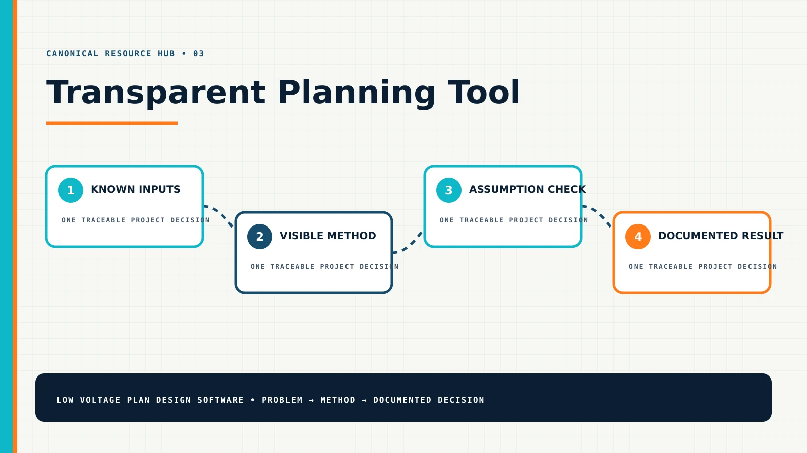
The six fields every planning calculation needs
| Field | What to record | Why it matters |
|---|---|---|
| Purpose | The decision the calculation supports | Prevents a correct formula from answering the wrong question |
| Inputs | Value, unit, source, date, and verification status | Separates field evidence from copied or assumed values |
| Method | Formula, sequence, rounding, and reference | Lets another person reproduce and challenge the result |
| Reserve | Service allowance, uncertainty, spare capacity, or growth | Makes contingency visible instead of hiding it inside a total |
| Limitations | Conditions the method does not prove | Directs optical, network, structural, electrical, code, or manufacturer review appropriately |
| Decision | Selected capacity, changed layout, allowance, alternate, or follow-up | Connects the math to the drawing, BOM, proposal, and approval |
Never mix units silently. Keep feet and meters, watts and volt-amperes, usable and raw storage, rack units and physical depth, or measured and allowance quantities clearly labeled. When a product-specific limit controls, verify the current manufacturer document rather than relying on an old project.
Three working examples you can use today
Worksheet 01 · PoE budget
Can the planned switch power the connected devices with a visible reserve?
Example inputs: eight devices at a planning load of 12.95 W each; 20% design reserve; switch PoE budget of 150 W.
8 × 12.95 W = 103.6 W connected load
103.6 W × 1.20 = 124.32 W planning requirement
150 W − 124.32 W = 25.68 W remaining planning capacity
Decision: The example fits the stated switch budget with 25.68 W remaining, but the designer still must confirm actual device requirements, PoE class/negotiation, port limits, switch operating constraints, uplink, UPS, environment, and growth. Record the result beside the PoE network map.
Worksheet 02 · Cable planning length
How do you keep measured route length separate from service and uncertainty allowances?
Example inputs: 42 m measured horizontal route; 4 m vertical transition at each end; 3 m service allowance at each end; 10% uncertainty because one ceiling area was inaccessible.
42 m + 8 m vertical + 6 m service = 56 m documented route basis
56 m × 10% = 5.6 m uncertainty allowance
56 m + 5.6 m = 61.6 m planning quantity
Decision: Carry 56 m as the documented route basis and 5.6 m as a separate allowance. Do not present 61.6 m as a field-verified distance. Connect route segment IDs and inaccessible areas to the cable pathway plan.
Worksheet 03 · Rack-space planning
Will the rack support planned equipment, cable management, service, and growth?
Example inputs: 2U patch panels, 2U horizontal cable management, 1U switch, 2U recorder/controller equipment, 2U UPS; add 20% growth and round up to a practical rack size.
2U + 2U + 1U + 2U + 2U = 9U planned equipment
9U × 1.20 = 10.8U minimum planning capacity
Round up: evaluate a 12U or larger rack against depth, load, airflow, power, access, and future work
Decision: A 12U rack may satisfy the unit count, but rack depth, equipment dimensions, weight, heat, door clearance, cable bend radius, grounding, power, UPS runtime, and service access can require a different selection. Use the telecom rack layout guide.
Choose the check that can change the next decision
Camera planning
Scene and storage assumptions
Record scene purpose, distance, width, light, motion, lens, resolution, frame rate, compression, retention, recording mode, redundancy, and usable capacity before estimating performance.
Network planning
PoE, ports, uplinks, and ownership
Reconcile powered-device load, port count, switch budget, spare ports, uplink capacity, VLAN responsibility, internet handoff, UPS, and growth.
Pathway planning
Routes, fill, transitions, and difficult conditions
Separate measured segments from vertical transitions, service loops, inaccessible areas, penetrations, shared routes, responsibility, and allowance.
Rack planning
Units, depth, heat, power, and access
Count more than U-space: verify dimensions, weight, mounting, ventilation, cable management, power, grounding, door swing, service clearance, and expansion.
BOM reconciliation
Devices, accessories, labor, and exclusions
Trace every quantity to a plan, schedule, calculation, allowance, alternate, or customer responsibility before it appears in the proposal.
AV coordination
Geometry, signal, network, and commissioning
Keep room geometry, sources, destinations, formats, transport, DSP, amplification, control, rack, cabling, power, and validation evidence connected.
Put the result where the project can use it
- Add the tool name, version or method date, project identifier, author, and reviewer.
- List every input with its unit, source, verification status, and date.
- Show the formula or decision sequence and preserve unrounded intermediate values where rounding matters.
- Separate measured quantity, design reserve, waste, uncertainty, future capacity, and commercial allowance.
- Identify the plan devices, pathway segments, rack, switch, door, zone, or proposal rows affected.
- State what must be confirmed through field measurement, manufacturer data, qualified design, testing, commissioning, or AHJ review.
A result that lives only in a calculator screen is easy to lose. Attach the documented basis to the approved plan revision and carry changed quantities into the estimate and proposal together.
Authoritative reference starting points
Use these sources to verify current terminology, practices, product context, and standards direction. Confirm the edition, jurisdiction, manufacturer requirements, and project applicability before relying on any external reference.
- Cisco campus LAN and WLAN design guide — network, wireless, switching, capacity, and PoE context
- ONVIF profiles — interoperability profile context for IP physical-security products
- ONVIF cybersecurity recommendations — IP physical-security cybersecurity review context