
Low-Voltage Field Reference • Wire & pinout diagram
Fiber Optic 12-Color Code Diagram for Strands, Tubes and Positions
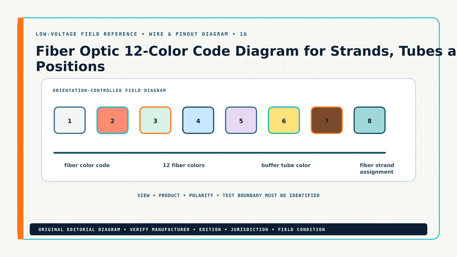
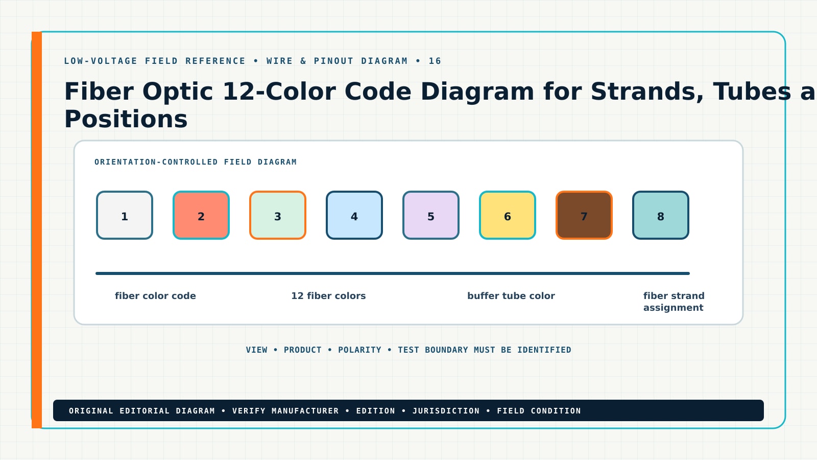
The common 12-position fiber color sequence is used to identify fibers and buffer tubes, then repeats in larger constructions with additional group identification. It is an administration convention—not a substitute for the exact cable manufacturer’s construction sheet and project assignment schedule.
Direct answer
fiber optic 12 color code: the practical answer
The common 12-position fiber color sequence is used to identify fibers and buffer tubes, then repeats in larger constructions with additional group identification. It is an administration convention—not a substitute for the exact cable manufacturer’s construction sheet and project assignment schedule.
For a working contractor, the value of this diagram is its ability to turn a wiring convention into an orientation-controlled installation record. Use the sequence scope → orientation → conductors → termination → test. Never treat an editorial drawing as a manufacturer terminal diagram.
What this changes in the design package
Fiber Optic 12-Color Code Diagram for Strands, Tubes and Positions should change at least one controlled project record. On a floor plan, identify the physical location or route affected by cable manufacturer and part number and fiber count and construction. On the riser or signal-flow drawing, show how the selected equipment, pathway, power and communications relationships support the intended outcome. In the schedule, preserve the exact data needed to buy, configure, install and test the system.
Plan
Show the device, route, zone or interface in context. Use stable IDs rather than relying on a symbol alone, and flag any assumption that can change quantity or performance.
Riser or schematic
Show origin, destination, intervening equipment, shared infrastructure and interface responsibility. A diagram should expose relationships the floor plan cannot show clearly.
Schedule
Record tube, ribbon or loose-tube grouping, connector and panel positions, project naming convention and existing plant records where they can be reviewed and revised without redrawing the entire plan.
Proposal
State the verified design basis, named allowances, exclusions, owner/IT/electrical dependencies, testing method and the event that triggers a change order.
Field method
A repeatable diagram workflow
Start with the exact product and the viewing orientation. Work from documented terminals and conductor identities, then prove the installed result with the appropriate test.
- 1. verify the jacket print and construction sheet.
- 2. map physical groups before splicing.
- 3. inspect both ends of the cable.
- 4. record tested strand assignments.
After the final step, repeat the original operating scenario. A correction is not complete until the system passes the required function, the drawing and schedule match the installed condition, and the handoff record identifies what changed.
Decision and evidence table
| Question | Evidence to collect | Where to record it | Acceptance signal |
|---|---|---|---|
| What controls cable manufacturer and part number? | verify the jacket print and construction sheet; use exact model, reading, setting, photo or log evidence. | strand assignment schedule, keyed to the same device/cable/door/zone ID. | The reviewed record and field condition agree, with no unresolved assumption hidden as fact. |
| What controls fiber count and construction? | map physical groups before splicing; use exact model, reading, setting, photo or log evidence. | splice matrix, keyed to the same device/cable/door/zone ID. | The reviewed record and field condition agree, with no unresolved assumption hidden as fact. |
| What controls tube, ribbon or loose-tube grouping? | inspect both ends of the cable; use exact model, reading, setting, photo or log evidence. | panel-port schedule, keyed to the same device/cable/door/zone ID. | The reviewed record and field condition agree, with no unresolved assumption hidden as fact. |
| What controls connector and panel positions? | record tested strand assignments; use exact model, reading, setting, photo or log evidence. | OTDR/OLTS record, keyed to the same device/cable/door/zone ID. | The reviewed record and field condition agree, with no unresolved assumption hidden as fact. |
Keep evidence close to the decision it supports. A screenshot without an equipment ID, a cable test without the cable identifier, or a code note without edition and jurisdiction is difficult to audit later.
Technical deep dive
Six controls that make fiber color code defensible
1. cable manufacturer and part number
reconcile cable manufacturer and part number before the team commits 12 fiber colors to the drawing. Identify who supplied the value, how current it is, which exact device, cable, interface, door, zone or route it controls, and what would invalidate it. If the answer comes from a product sheet, retain the model and revision. If it comes from a field observation, retain the location, timestamp, instrument or screen, and technician. If it comes from a requirement, retain jurisdiction, edition and reviewer.
Use this checkpoint to verify the jacket print and construction sheet. Compare the evidence with the intended structured cabling outcome and the accepted project baseline. A discrepancy should become a named issue with an owner and due date; it should not be buried in a markup. Watch specifically for counting colors without identifying the group, because that failure can create a plausible-looking plan while breaking the installation, test or commercial handoff.
Close the checkpoint in the strand assignment schedule. Tie it to fiber color code and 12 fiber colors with the same stable identifier used on the plan and schedule. The reviewer should be able to see the source, selected value, status, exception and acceptance result without reconstructing the designer’s assumptions from email.
2. fiber count and construction
challenge fiber count and construction before the team commits buffer tube color to the drawing. Identify who supplied the value, how current it is, which exact device, cable, interface, door, zone or route it controls, and what would invalidate it. If the answer comes from a product sheet, retain the model and revision. If it comes from a field observation, retain the location, timestamp, instrument or screen, and technician. If it comes from a requirement, retain jurisdiction, edition and reviewer.
Use this checkpoint to map physical groups before splicing. Compare the evidence with the intended structured cabling outcome and the accepted project baseline. A discrepancy should become a named issue with an owner and due date; it should not be buried in a markup. Watch specifically for assuming every ribbon or tube repeats identically, because that failure can create a plausible-looking plan while breaking the installation, test or commercial handoff.
Close the checkpoint in the splice matrix. Tie it to fiber color code and buffer tube color with the same stable identifier used on the plan and schedule. The reviewer should be able to see the source, selected value, status, exception and acceptance result without reconstructing the designer’s assumptions from email.
3. tube, ribbon or loose-tube grouping
preserve tube, ribbon or loose-tube grouping before the team commits fiber strand assignment to the drawing. Identify who supplied the value, how current it is, which exact device, cable, interface, door, zone or route it controls, and what would invalidate it. If the answer comes from a product sheet, retain the model and revision. If it comes from a field observation, retain the location, timestamp, instrument or screen, and technician. If it comes from a requirement, retain jurisdiction, edition and reviewer.
Use this checkpoint to inspect both ends of the cable. Compare the evidence with the intended structured cabling outcome and the accepted project baseline. A discrepancy should become a named issue with an owner and due date; it should not be buried in a markup. Watch specifically for splicing by color without cable direction, because that failure can create a plausible-looking plan while breaking the installation, test or commercial handoff.
Close the checkpoint in the panel-port schedule. Tie it to fiber color code and fiber strand assignment with the same stable identifier used on the plan and schedule. The reviewer should be able to see the source, selected value, status, exception and acceptance result without reconstructing the designer’s assumptions from email.
4. connector and panel positions
establish connector and panel positions before the team commits optical cable identification to the drawing. Identify who supplied the value, how current it is, which exact device, cable, interface, door, zone or route it controls, and what would invalidate it. If the answer comes from a product sheet, retain the model and revision. If it comes from a field observation, retain the location, timestamp, instrument or screen, and technician. If it comes from a requirement, retain jurisdiction, edition and reviewer.
Use this checkpoint to record tested strand assignments. Compare the evidence with the intended structured cabling outcome and the accepted project baseline. A discrepancy should become a named issue with an owner and due date; it should not be buried in a markup. Watch specifically for omitting dark-fiber ownership and reserve, because that failure can create a plausible-looking plan while breaking the installation, test or commercial handoff.
Close the checkpoint in the OTDR/OLTS record. Tie it to fiber color code and optical cable identification with the same stable identifier used on the plan and schedule. The reviewer should be able to see the source, selected value, status, exception and acceptance result without reconstructing the designer’s assumptions from email.
5. project naming convention
measure project naming convention before the team commits fiber schedule to the drawing. Identify who supplied the value, how current it is, which exact device, cable, interface, door, zone or route it controls, and what would invalidate it. If the answer comes from a product sheet, retain the model and revision. If it comes from a field observation, retain the location, timestamp, instrument or screen, and technician. If it comes from a requirement, retain jurisdiction, edition and reviewer.
Use this checkpoint to verify the jacket print and construction sheet. Compare the evidence with the intended structured cabling outcome and the accepted project baseline. A discrepancy should become a named issue with an owner and due date; it should not be buried in a markup. Watch specifically for counting colors without identifying the group, because that failure can create a plausible-looking plan while breaking the installation, test or commercial handoff.
Close the checkpoint in the strand assignment schedule. Tie it to fiber color code and fiber schedule with the same stable identifier used on the plan and schedule. The reviewer should be able to see the source, selected value, status, exception and acceptance result without reconstructing the designer’s assumptions from email.
6. existing plant records
trace existing plant records before the team commits fiber color code to the drawing. Identify who supplied the value, how current it is, which exact device, cable, interface, door, zone or route it controls, and what would invalidate it. If the answer comes from a product sheet, retain the model and revision. If it comes from a field observation, retain the location, timestamp, instrument or screen, and technician. If it comes from a requirement, retain jurisdiction, edition and reviewer.
Use this checkpoint to map physical groups before splicing. Compare the evidence with the intended structured cabling outcome and the accepted project baseline. A discrepancy should become a named issue with an owner and due date; it should not be buried in a markup. Watch specifically for assuming every ribbon or tube repeats identically, because that failure can create a plausible-looking plan while breaking the installation, test or commercial handoff.
Close the checkpoint in the splice matrix. Tie it to fiber color code and fiber color code with the same stable identifier used on the plan and schedule. The reviewer should be able to see the source, selected value, status, exception and acceptance result without reconstructing the designer’s assumptions from email.
Field-capture worksheet
Before leaving the site, collect enough evidence that another qualified person can reconstruct the decision. Start with the site, floor, room and stable asset ID. Record the date, technician and current drawing revision. Photograph the overall context before taking close-ups, and place a readable label or reference in the image when practical.
- Identity
- Exact manufacturer, model, firmware or listing, terminal names, cable ID, panel/port/zone/door address, and the related plan symbol.
- Observed state
- What the user reported, what the technician reproduced, timestamps, LEDs or messages, logs, settings and whether the condition is continuous or intermittent.
- Measured state
- Applicable voltage, current, resistance, optical level, cable result, protocol status, signal format or environmental condition, including the instrument and test boundary.
- Change control
- The one change made, authorization, before/after evidence, temporary workaround, regression checks and any effect on other devices or shared infrastructure.
For this topic, call out cable manufacturer and part number, tube, ribbon or loose-tube grouping and project naming convention. Use the vocabulary fiber color code, 12 fiber colors, buffer tube color consistently so the field note, drawing, schedule and proposal can be found together.
Worked field example
From an uncertain condition to a controlled record
A project manager receives a report involving fiber color code. The available plan shows a symbol, but it does not identify cable manufacturer and part number, fiber count and construction or tube, ribbon or loose-tube grouping. Instead of pricing or repairing from the incomplete symbol, the team opens a single issue record and assigns the affected equipment, cable or location a stable ID.
The technician collects the current settings, model information, photos and measured state. The designer compares that evidence with the selected equipment documentation and the current authoritative sources listed below. The estimator separates verified scope from allowances. The project manager records who owns any external dependency, such as an electrical circuit, network policy, door hardware condition, AHJ decision or owner-furnished device.
The corrected package includes the strand assignment schedule, splice matrix and panel-port schedule. The team then repeats the operating test under the same conditions that produced the original question. That closed loop turns 12 fiber colors and buffer tube color from search terms into traceable project decisions instead of isolated notes.
Common failure modes—and why they happen
Failure 01
counting colors without identifying the group
This shortcut removes context from the decision. Correct it by returning to the project-specific input, documenting the selected basis, and repeating the affected acceptance test.
Failure 02
assuming every ribbon or tube repeats identically
This shortcut removes context from the decision. Correct it by returning to the project-specific input, documenting the selected basis, and repeating the affected acceptance test.
Failure 03
splicing by color without cable direction
This shortcut removes context from the decision. Correct it by returning to the project-specific input, documenting the selected basis, and repeating the affected acceptance test.
Failure 04
omitting dark-fiber ownership and reserve
This shortcut removes context from the decision. Correct it by returning to the project-specific input, documenting the selected basis, and repeating the affected acceptance test.
When a failure involves regulated life safety, egress, listing, energized work, public-safety radio, or code interpretation, stop at the boundary of your authorization. Escalate to the responsible qualified party and preserve the condition and evidence.
Minimum contractor deliverables
A useful answer survives the handoff from design to estimating, proposal, installation and closeout. At minimum, create the following:
- strand assignment schedule.
- splice matrix.
- panel-port schedule.
- OTDR/OLTS record.
Each deliverable should show the project, revision, author, review status and the identity of the system element it controls. If a value is not verified, label it as an assumption, allowance, pending submittal or owner/AHJ decision. Do not let a blank field become an accidental commitment.
How to carry the answer into scope and proposal language
Describe the outcome first: what the customer will receive, where it applies and how it will be tested. Then name the basis used for fiber color code, including the controlling drawing revision and selected equipment data. Include the labor and documentation needed to produce strand assignment schedule and splice matrix.
Separate dependencies explicitly. Examples include usable owner drawings, accessible ceilings, working branch power, network addressing and policy, compatible owner equipment, door hardware readiness, permits, shutdown windows, AHJ review and access to occupied areas. If one of those facts is unknown, write an allowance or qualification and define how the price changes when the fact is confirmed.
Finish with acceptance: identify who witnesses the test, what evidence is retained and which result constitutes completion. This makes the page commercially useful without turning it into a product pitch.
Commissioning, handoff and future service
Commissioning should prove the designed function, not simply show that equipment turns on. Run the accepted scenario, an expected failure or trouble state, recovery, and any interface that crosses to network, electrical, fire alarm, door hardware, controls or owner systems. Save results against stable IDs and the approved revision.
At handoff, give the owner the strand assignment schedule, splice matrix, final configuration, approved substitutions, warranties and the contact path for unresolved external responsibilities. Remove default credentials and temporary access where applicable. Explain which changes can invalidate the result—for example a new firmware release, equipment replacement, changed speaker tap, moved camera, added cable, revised AHJ direction or modified switch policy.
Future service begins by comparing the current condition with this accepted baseline. If the record is missing, recreate it before making broad changes. That discipline reduces repeated troubleshooting, protects proposal scope, and lets the next technician distinguish a design issue from a later operational change.
Frequently asked questions
What should I verify first?
Start with cable manufacturer and part number and fiber count and construction. Establish the exact product, project location and current system state before applying a diagram or changing configuration.
Can I use this page as a construction detail?
Use it as an editorial planning and verification aid. Convert it into a project detail only after reconciling the manufacturer instructions, adopted requirements, approved submittals and responsible professional or AHJ direction.
What belongs in the closeout package?
Include strand assignment schedule, splice matrix, panel-port schedule, OTDR/OLTS record, plus test evidence, deviations, final settings and the identity of the person or authority that accepted the result.
What should I read next?
Continue with T568A vs T568B Wiring Diagram and Termination Guide, RJ45 Pinout Orientation: Plug, Jack and Drawing Views, Fiber Connector Color Codes: What Aqua, Blue, Green and Other Colors Mean, 110 Block Termination Diagram: Pair Order and Cross-Connect Workflow and the Structured Cabling design software resource.
Authoritative references and how to use them
These links are starting points for current primary-source information. Confirm the current edition, product revision, publication status, jurisdiction and applicability. Accessed for this release on 2026-08-08.
- Fiber Optics Association color codes — use the source to verify terminology, conformance, published requirements or manufacturer-specific behavior; do not substitute this summary for the controlling document.
- Fiber Optics Association standards guide — use the source to verify terminology, conformance, published requirements or manufacturer-specific behavior; do not substitute this summary for the controlling document.
- TIA Standards and Technology — use the source to verify terminology, conformance, published requirements or manufacturer-specific behavior; do not substitute this summary for the controlling document.