

Intercom, Paging & Clock contractor resource
Intercom, Paging and Clock System Design Software
Coordinate door communication, paging zones, speakers, call stations, master stations, clocks, head-end equipment, network, power, schedules, and acceptance scenarios. This practical guide explains what to document, how to structure the drawing set, where coordination fails, what the proposal must carry, and how to evaluate software against a real contractor workflow.
What intercom paging clock system design software must solve
Someone searching for intercom paging clock system design software is rarely looking for a generic drawing program. The practical need is a controlled way to translate customer intent and field conditions into a design another estimator, installer, reviewer, programmer, IT administrator, and customer can understand. The software must help the contractor preserve decisions as the project moves from discovery to proposal and from approved scope to installation.
For intercom, paging & clock, the core promise is specific: Coordinate door communication, paging zones, speakers, call stations, master stations, clocks, head-end equipment, network, power, schedules, and acceptance scenarios. That means the plan cannot be an attractive background with unconnected icons. Each important item needs a stable identity and a reason to exist. Its location must agree with schedules and schematics; its infrastructure must be visible; its quantity must reach the estimate; and its open decisions must be owned.
The best result is query-complete rather than keyword-heavy. A customer should be able to use this page to understand the deliverables, ask better questions, recognize missing scope, and select a workflow. A contractor should be able to turn the same guidance into a survey checklist, drawing outline, coordination meeting agenda, estimating review, and acceptance plan.
The design record should answer six groups of questions
The table below connects the design scope to a reviewable output. The exact document set depends on project size, contract, jurisdiction, risk, and the responsible designer. The principle stays the same: put information where it can be checked and cross-reference it with stable identifiers.
| Decision group | What to document | Useful output |
|---|---|---|
| Door, help-point | Door, help-point, classroom, staff, master, and emergency communication stations by purpose and user | Communication-device floor plan |
| Paging speakers, horns | Paging speakers, horns, strobes, displays, zone controllers, amplifiers, microphones, and interfaces | Paging/clock zone schedule |
| Clock type, display | Clock type, display, location, time source, correction method, network or wiring, and power relationship | Head-end and network diagram |
| Audio zones, priorities | Audio zones, priorities, emergency override, scheduled events, bells, tones, announcements, and content ownership | Priority and event matrix |
| Head-end servers, controllers | Head-end servers, controllers, DSP, amplifiers, network, PoE, power, UPS, racks, and administration | Cable and port schedule |
| Cable, pathway | Cable, pathway, device schedule, programming, testing, intelligibility/audibility review, training, and acceptance | Acceptance-scenario checklist |
Recommended deliverables
Communication-device floor plan
Communication-device floor plan. Record the value, source, verification status, responsible party, and revision so another person can audit the decision.
Paging/clock zone schedule
Paging/clock zone schedule. Show the relationship on the correct drawing or schedule instead of burying it in a note that cannot be traced.
Head-end and network diagram
Head-end and network diagram. Separate observed conditions from design assumptions and customer choices; price uncertainty as an allowance or exclusion when needed.
Priority and event matrix
Priority and event matrix. Carry stable identifiers into the takeoff, proposal, installation record, test evidence, and closeout documents.
Cable and port schedule
Cable and port schedule. Review capacity, compatibility, access, serviceability, future change, and failure behavior before the product is committed.
Acceptance-scenario checklist
Acceptance-scenario checklist. Assign ownership at the interface with architecture, electrical, IT, operations, other vendors, and the authority having jurisdiction.
A floor plan is usually the location index, not the entire design. When lines or notes make it hard to answer a question, move the information to the proper schedule, schematic, riser, elevation, matrix, narrative, or calculation worksheet. Then place a clear reference on both documents so the reader can move between them.
Intercom, Paging & Clock project review worksheet
Use these six prompts during discovery, drawing review, estimating, and handoff. Write the answer in project language, identify its source, and mark whether it is verified, selected, assumed, excluded, or assigned to another party.
1. Survey evidence
Review this system-specific scope: Door, help-point, classroom, staff, master, and emergency communication stations by purpose and user.
Connect it to this coordination condition: User groups, operating hours, reception, security, classroom or facility workflow, privacy, accessibility, and emergency procedures. The review is complete only when the plan, Communication-device floor plan, quantity basis, responsibility, and verification record describe the same decision. If the answer depends on a field condition, product selection, authority, owner policy, or third-party system, name that dependency instead of converting it into an unsupported promise.
2. Drawing decision
Review this system-specific scope: Paging speakers, horns, strobes, displays, zone controllers, amplifiers, microphones, and interfaces.
Connect it to this coordination condition: Acoustic environment, background noise, room volume, partitions, outdoor areas, speaker mounting, and coverage review. The review is complete only when the plan, Paging/clock zone schedule, quantity basis, responsibility, and verification record describe the same decision. If the answer depends on a field condition, product selection, authority, owner policy, or third-party system, name that dependency instead of converting it into an unsupported promise.
3. Infrastructure dependency
Review this system-specific scope: Clock type, display, location, time source, correction method, network or wiring, and power relationship.
Connect it to this coordination condition: Door hardware, access control, video, call routing, attendant station, mobile client, recording policy, and release responsibility. The review is complete only when the plan, Head-end and network diagram, quantity basis, responsibility, and verification record describe the same decision. If the answer depends on a field condition, product selection, authority, owner policy, or third-party system, name that dependency instead of converting it into an unsupported promise.
4. Commercial consequence
Review this system-specific scope: Audio zones, priorities, emergency override, scheduled events, bells, tones, announcements, and content ownership.
Connect it to this coordination condition: Network, multicast, VLAN, QoS, PoE, servers, licenses, cybersecurity, time synchronization, and IT ownership. The review is complete only when the plan, Priority and event matrix, quantity basis, responsibility, and verification record describe the same decision. If the answer depends on a field condition, product selection, authority, owner policy, or third-party system, name that dependency instead of converting it into an unsupported promise.
5. Field verification
Review this system-specific scope: Head-end servers, controllers, DSP, amplifiers, network, PoE, power, UPS, racks, and administration.
Connect it to this coordination condition: Emergency communication, fire/life-safety boundaries, priorities, supervision, backup power, qualified review, and AHJ requirements. The review is complete only when the plan, Cable and port schedule, quantity basis, responsibility, and verification record describe the same decision. If the answer depends on a field condition, product selection, authority, owner policy, or third-party system, name that dependency instead of converting it into an unsupported promise.
6. Acceptance evidence
Review this system-specific scope: Cable, pathway, device schedule, programming, testing, intelligibility/audibility review, training, and acceptance.
Connect it to this coordination condition: Message content, languages, schedules, bells, tones, training, testing, maintenance, and owner administration. The review is complete only when the plan, Acceptance-scenario checklist, quantity basis, responsibility, and verification record describe the same decision. If the answer depends on a field condition, product selection, authority, owner policy, or third-party system, name that dependency instead of converting it into an unsupported promise.
Trace one intercom, paging & clock decision through the record
For a K-12 school addition with classrooms, corridors, outdoor play areas, reception, secure vestibule, and synchronized clocks, use the following chain as a document-control exercise. The entries are not generic fields: each one ties a discipline-specific design question to a deliverable and a commercial or field consequence.
| Design question | Primary record | Traceability test |
|---|---|---|
| Door, help-point, classroom, staff, master, and emergency communication stations by purpose and user | Communication-device floor plan | Find the matching Door station IC-01 relationship, then identify the quantity, owner, verification status, and effect of a revision to User groups, operating hours, reception, security, classroom or facility workflow, privacy, accessibility, and emergency procedures. |
| Paging speakers, horns, strobes, displays, zone controllers, amplifiers, microphones, and interfaces | Paging/clock zone schedule | Find the matching Paging zone PZ-1 relationship, then identify the quantity, owner, verification status, and effect of a revision to Acoustic environment, background noise, room volume, partitions, outdoor areas, speaker mounting, and coverage review. |
| Clock type, display, location, time source, correction method, network or wiring, and power relationship | Head-end and network diagram | Find the matching Master station relationship, then identify the quantity, owner, verification status, and effect of a revision to Door hardware, access control, video, call routing, attendant station, mobile client, recording policy, and release responsibility. |
| Audio zones, priorities, emergency override, scheduled events, bells, tones, announcements, and content ownership | Priority and event matrix | Find the matching Head-end controller relationship, then identify the quantity, owner, verification status, and effect of a revision to Network, multicast, VLAN, QoS, PoE, servers, licenses, cybersecurity, time synchronization, and IT ownership. |
| Head-end servers, controllers, DSP, amplifiers, network, PoE, power, UPS, racks, and administration | Cable and port schedule | Find the matching Network time source relationship, then identify the quantity, owner, verification status, and effect of a revision to Emergency communication, fire/life-safety boundaries, priorities, supervision, backup power, qualified review, and AHJ requirements. |
| Cable, pathway, device schedule, programming, testing, intelligibility/audibility review, training, and acceptance | Acceptance-scenario checklist | Find the matching Door station IC-01 relationship, then identify the quantity, owner, verification status, and effect of a revision to Message content, languages, schedules, bells, tones, training, testing, maintenance, and owner administration. |
The chain is successful when a reviewer can move in both directions: from a customer outcome to the drawing and proposal, and from a field quantity back to the approved purpose and evidence. If either direction fails, add the missing identity, cross-reference, schedule field, assumption, or responsibility before approval.
A contractor workflow from requirement to accepted scope
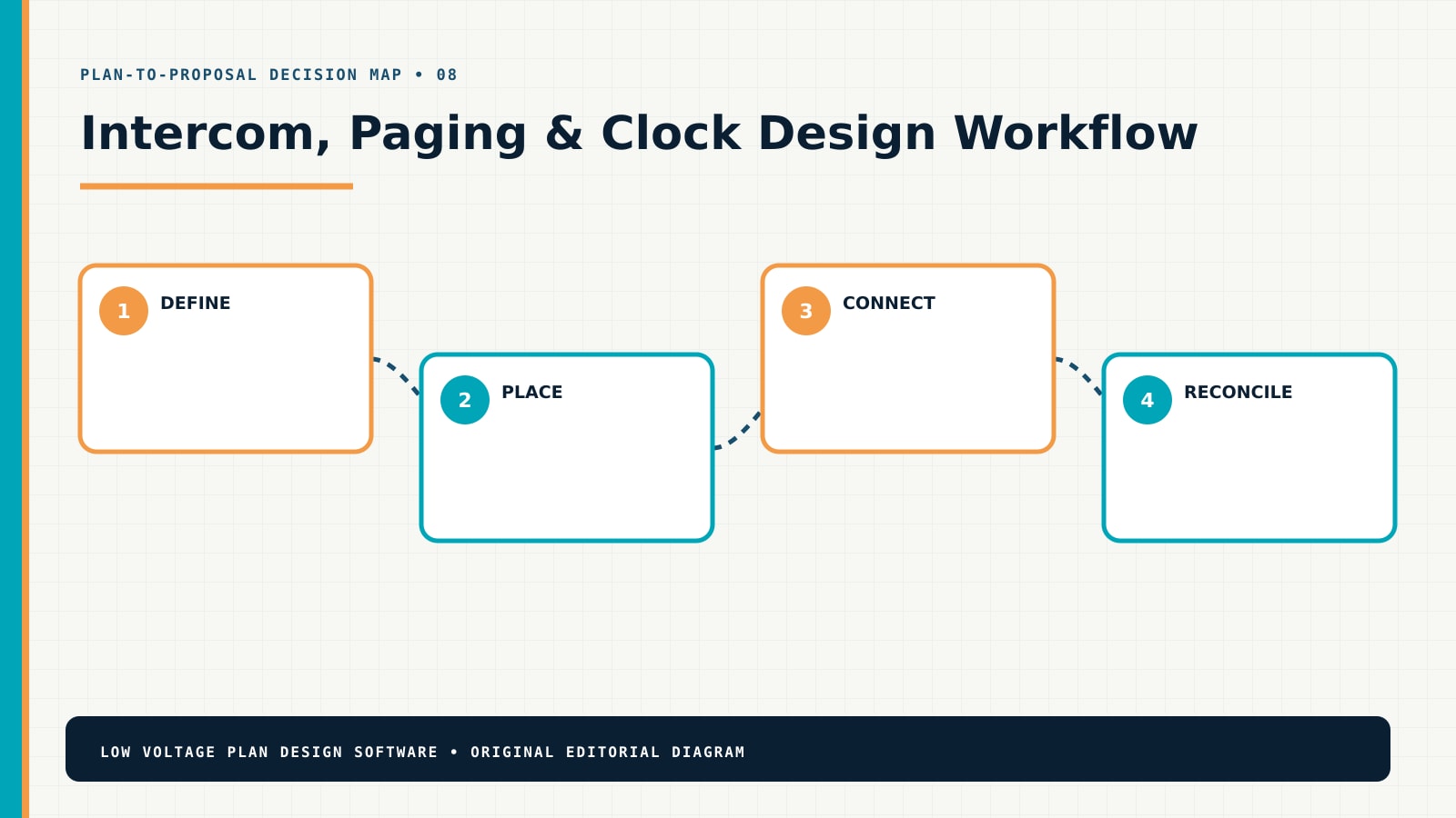
This four-stage sequence keeps design detail proportional to the decision. Early work can show intent and uncertainty. Later work should resolve product-specific interfaces, quantities, installation methods, configuration, testing, and handoff. Do not imply that an early sales layout is permit-ready, engineered, or field-verified unless it actually is.
- Define the operating outcome.Define who communicates with whom, from where, under which normal, emergency, accessibility, privacy, and operational conditions. At this stage, reject anonymous quantities: each important element needs a location, purpose, relationship, status, or documented basis.
- Place and identify the system.Lay out stations, speakers, displays, clocks, interfaces, zones, and head-end equipment from the approved use cases. At this stage, reject anonymous quantities: each important element needs a location, purpose, relationship, status, or documented basis.
- Connect infrastructure and ownership.Map devices to circuits, network ports, PoE, amplifiers, controllers, time sources, pathways, and serving rooms. At this stage, reject anonymous quantities: each important element needs a location, purpose, relationship, status, or documented basis.
- Reconcile scope and handoff.Reconcile audibility or intelligibility review, programming, content, schedules, training, testing, BOM, proposal, and closeout. At this stage, reject anonymous quantities: each important element needs a location, purpose, relationship, status, or documented basis.
Coordination questions to close before the proposal
User groups, operating hours, reception, security, classroom or facility workflow, privacy, accessibility, and emergency procedures
User groups, operating hours, reception, security, classroom or facility workflow, privacy, accessibility, and emergency procedures. Record the value, source, verification status, responsible party, and revision so another person can audit the decision.
Acoustic environment, background noise, room volume, partitions, outdoor areas, speaker mounting, and coverage review
Acoustic environment, background noise, room volume, partitions, outdoor areas, speaker mounting, and coverage review. Show the relationship on the correct drawing or schedule instead of burying it in a note that cannot be traced.
Door hardware, access control, video, call routing, attendant station, mobile client, recording policy, and release responsibility
Door hardware, access control, video, call routing, attendant station, mobile client, recording policy, and release responsibility. Separate observed conditions from design assumptions and customer choices; price uncertainty as an allowance or exclusion when needed.
Network, multicast, VLAN, QoS, PoE, servers, licenses, cybersecurity, time synchronization, and IT ownership
Network, multicast, VLAN, QoS, PoE, servers, licenses, cybersecurity, time synchronization, and IT ownership. Carry stable identifiers into the takeoff, proposal, installation record, test evidence, and closeout documents.
Emergency communication, fire/life-safety boundaries, priorities, supervision, backup power, qualified review, and AHJ requirements
Emergency communication, fire/life-safety boundaries, priorities, supervision, backup power, qualified review, and AHJ requirements. Review capacity, compatibility, access, serviceability, future change, and failure behavior before the product is committed.
Message content, languages, schedules, bells, tones, training, testing, maintenance, and owner administration
Message content, languages, schedules, bells, tones, training, testing, maintenance, and owner administration. Assign ownership at the interface with architecture, electrical, IT, operations, other vendors, and the authority having jurisdiction.
Coordination is part of the product. A device may be inexpensive while its pathway, power, network, mounting, licensing, access, programming, firestopping, outage window, or third-party interface carries the real cost. The drawing set should expose those dependencies early enough for a responsible party to answer them.
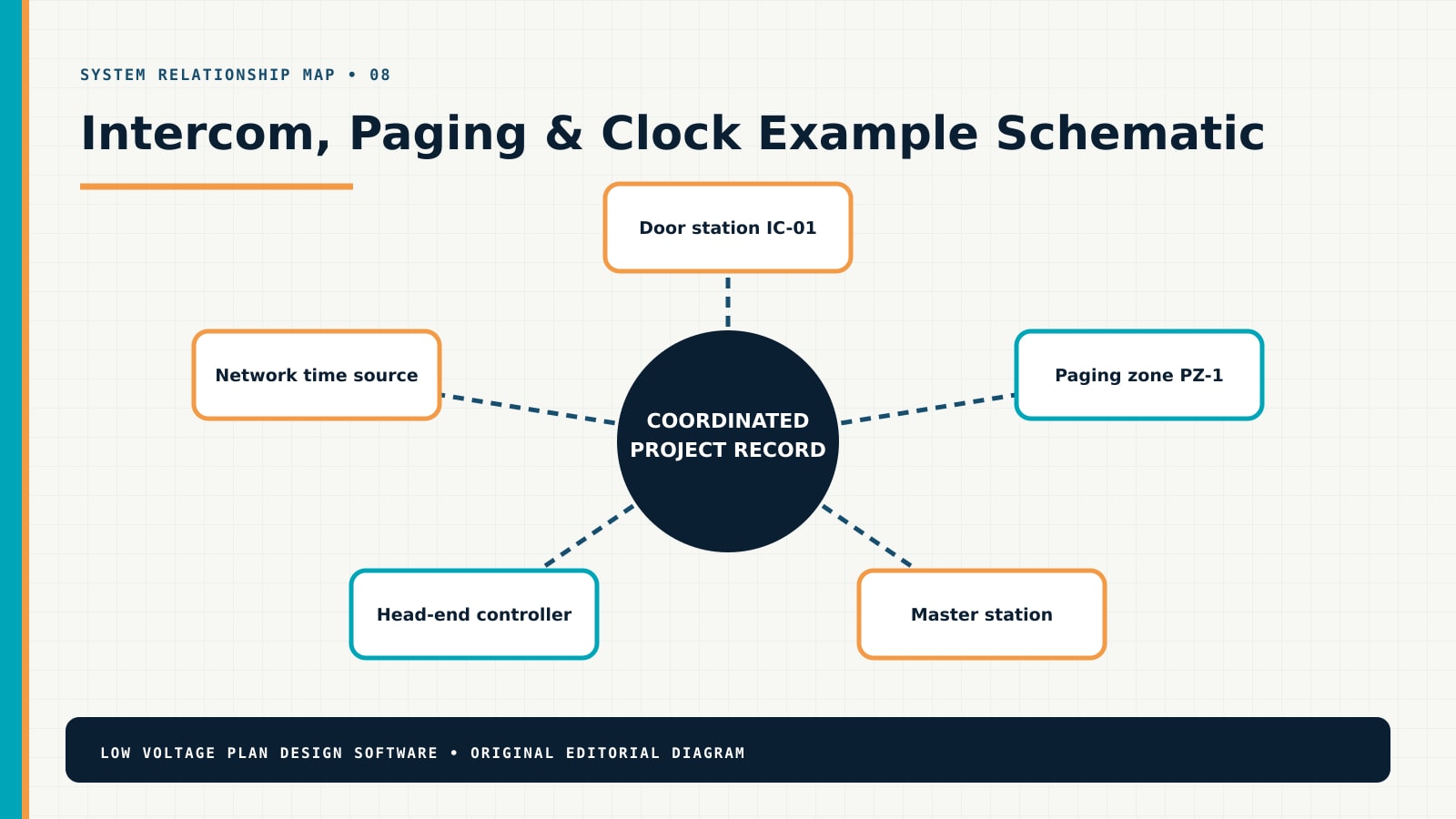
Worked example: a K-12 school addition with classrooms, corridors, outdoor play areas, reception, secure vestibule, and synchronized clocks
Starting problem. The floor plan contains speaker symbols but no paging zones, call paths, priority rules, head-end relationship, clock correction method, or emergency-system boundary.
Design response. The design maps communication use cases to zones and stations, separates routine and emergency functions, connects devices to head-end/network/power, and creates a scenario-based acceptance checklist.
Commercial and field result. The proposal and commissioning plan cover equipment, endpoints, cable, PoE, amplification, programming, messages, training, and tests without treating every speaker as an interchangeable symbol.
The example is not a product recommendation or a quantity template. Its value is the reasoning chain: define the operating outcome, identify what is verified, document relationships, expose dependencies, and reconcile the resulting work to an issued revision. Reuse that method, but verify every location, dimension, product, code requirement, pathway, calculation, and responsibility on the actual project.
Example review checkpoints
- Can a reviewer explain why every major element exists and which customer outcome it supports?
- Can an estimator trace every major quantity to a plan, schedule, schematic, calculation, allowance, or explicit assumption?
- Can a field technician distinguish approved work, alternates, owner-furnished items, existing conditions, demolition, and unverified conditions?
- Can IT, electrical, architecture, operations, and other vendors see their interfaces without interpreting hidden design intent?
- Can the team record a change once, identify affected documents and quantities, obtain approval, and preserve the prior revision?
- Does the acceptance plan test operating outcomes and interfaces instead of confirming only that devices power on?
How to evaluate intercom paging clock system design software
Use a representative project instead of a polished demonstration. Recreate a real survey condition, one shared infrastructure dependency, one customer change, and one scope alternative. The evaluation should expose whether the tool supports decisions or simply makes drawing faster.
| Test | What good looks like | Warning sign |
|---|---|---|
| Baseline and revisions | Rooms, scale, field evidence, assumptions, issue status, and revisions remain visible and controlled. | A new background or duplicate file silently breaks identities and quantities. |
| Industry documentation | Plans, schedules, schematics, details, notes, and responsibility fields match the discipline. | Generic icons substitute for system relationships and deliverables. |
| Quantity traceability | Equipment, accessories, cable, infrastructure, licenses, labor, and options trace to the approved revision. | The estimate is a separate list that cannot be reconciled to the plan. |
| Customer scope | Inclusions, exclusions, allowances, alternatives, prerequisites, and decisions are understandable. | The proposal promises performance while hiding assumptions and third-party work. |
| Field handoff | Technicians receive stable IDs, current documents, verification items, change control, test expectations, and closeout structure. | Installers work from screenshots or sales notes without revision status. |
| Connected workflow | The plan can support proposal, follow-up, approval, change, and closeout without retyping the project. | Every workspace recreates customer, location, item, quantity, and status data. |
Common failure modes
- Device-count design: a quantity is selected before purpose, geometry, interfaces, or infrastructure are understood.
- Decorative schematic: lines show that boxes connect but omit ports, media, direction, protocol, power, ownership, or failure behavior.
- Invisible shared scope: racks, network, power, pathways, accounts, licensing, programming, and testing are assumed rather than assigned.
- Revision drift: plan, schedule, BOM, proposal, installer copy, and closeout record describe different versions of the project.
- False precision: unmeasured routes, unverified conditions, preliminary models, or early product choices are presented as confirmed facts.
- Weak acceptance: completion means “installed” instead of verified operating outcomes, interfaces, training, documentation, and owner approval.
Focused Intercom, Paging & Clock field answers
Use these two query-specific resources when the broad workflow is not enough. Each answer includes a contractor method, worked situation, unique diagram, proposal audit, internal reading path, authoritative references, and a direct connection back to this industry workflow.
School Intercom and Paging Zone Map: Rooms, Priorities and Emergency Interfaces
Map speakers, call stations, classrooms, offices, exterior areas, zones, bell schedules, priority sources, emergency interfaces, network, power, and acceptance by operating scenario.
Intercom System Wiring Diagram: Stations, Doors, Network, Power and Release
Build a manufacturer-aware intercom topology that shows stations, call buttons, door interfaces, relays, locks, network, power, cabling, licenses, call routing, and failure behavior.
Continue the research inside this publication
This canonical page is the industry entry point. Use the related resources below to move from selection into specific drawings, schedules, examples, and workflows. The links use adjacent search language intentionally so readers can follow the problem rather than return to a generic archive.
- distributed-audio floor-plan guide — use it to extend this page into the next documented decision.
- AV signal-flow guide — use it to extend this page into the next documented decision.
- cable schedule guide — use it to extend this page into the next documented decision.
- rack layout guide — use it to extend this page into the next documented decision.
- commercial AV discipline hub — use it to extend this page into the next documented decision.
Compare this discipline with all 22 low-voltage industry design software workflows, or start from the broader low-voltage disciplines hub. Use the design guides for methods, the plan examples for scenarios, the planning tools for transparent calculations, and the glossary for shared terminology.
Authoritative references to verify for this project
These links are starting points, not substitutes for the adopted code, contract documents, manufacturer instructions, licensed design, or authority approval. Confirm current editions, jurisdiction, product applicability, and project-specific requirements.
- AVIXA AV Glossary — audiovisual and communications terminology.
- TIA Standards — communications infrastructure context.
- Cisco Campus LAN and WLAN Design Guide — network and PoE design context.
Frequently asked questions
What should intercom paging clock system design software produce?
It should produce more than a diagram. A useful project record connects locations, identifiers, system relationships, schedules, infrastructure, assumptions, quantities, scope boundaries, review decisions, field changes, testing, and closeout evidence. For this discipline, the minimum useful set normally includes Communication-device floor plan, Paging/clock zone schedule, Head-end and network diagram, Priority and event matrix.
Can the software replace engineering, code review, or manufacturer design?
No. Documentation software helps a qualified team organize, communicate, reconcile, and revise the work. It does not grant a license, determine the adopted code, approve a regulated design, validate a proprietary calculation, or replace manufacturer instructions and authority review.
How should a contractor compare intercom, paging & clock design tools?
Test the real workflow. Begin with a survey change, place and identify representative elements, build a schedule or schematic, revise a shared dependency, reconcile quantities, produce customer-readable scope, and inspect the field handoff. A polished symbol library is not enough if identities, relationships, quantities, revisions, and approvals fall apart.
What information belongs on the floor plan?
Keep location-specific information on the plan: room, device or endpoint position, purpose, stable ID, mounting or orientation intent, nearby constraints, and cross-references. Move repeated attributes to schedules and system relationships to a riser, one-line, topology, signal flow, control diagram, or responsibility matrix.
How does this improve the proposal?
The proposal becomes explainable because devices, accessories, cable, infrastructure, licenses, labor, programming, testing, training, allowances, alternatives, and exclusions trace back to an approved design revision. When the drawing changes, the team can find the commercial effect instead of relying on memory.