
A low-voltage floor plan is a coordinated drawing that shows where devices belong, what each device is called, how cable reaches it, and how the plan connects to schedules, risers, quantities, and field work. A useful low-voltage plan does more than place symbols over an architectural background. It gives the estimator, installer, project manager, customer, and service technician the same traceable version of the system.
This guide explains a practical low voltage floor plan design workflow for security cameras, access control, structured cabling, network and Wi-Fi, audio/video, home theater, business voice, point of sale, and smart systems. The exact requirements vary by project, discipline, contract, manufacturer, jurisdiction, and authority having jurisdiction. Treat this as a documentation workflow—not a substitute for engineered design, adopted code, licensing, manufacturer instructions, or approved construction documents.
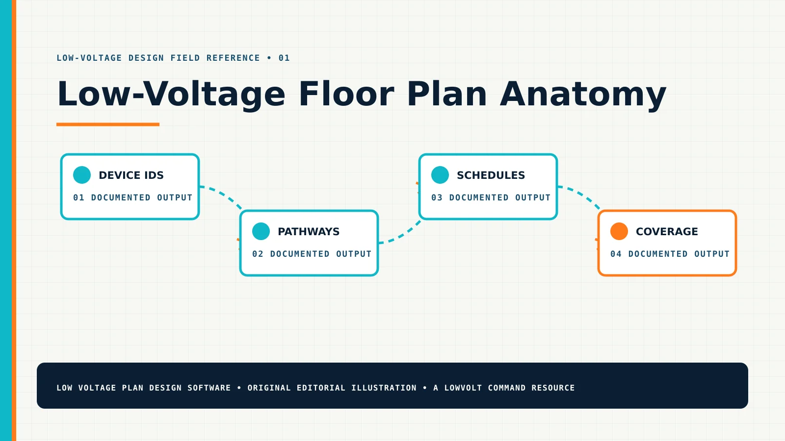
What belongs on a low-voltage floor plan?
The floor plan is the location-based member of the drawing set. It should answer five basic questions without forcing the reader to guess:
- Where is the device? Show a clear symbol at the intended wall, ceiling, rack, door, workstation, exterior mounting point, or equipment area.
- What is it? Give every planned device a readable type and unique identifier that agrees with the legend and schedule.
- What is it intended to accomplish? Communicate coverage, controlled opening, serving area, user location, zone, or other design intent when a symbol alone cannot do so.
- How does it connect? Reference the associated pathway, cable, controller, switch, panel, rack, riser, or signal-flow document.
- Where is the supporting information? Make it easy to find mounting notes, device attributes, quantities, alternates, scope boundaries, and coordination requirements.
A contractor may produce a simple one-sheet plan for a small project or a multi-sheet coordinated set for a large facility. The drawing count is less important than whether the information remains legible and traceable.
Start with a controlled architectural base
Reliable low-voltage floor plan design begins with the best available background. Request a current architectural PDF, CAD export, or other authorized base drawing. Confirm the building area, floor, revision, orientation, room names, door numbers, scale, and known differences between the drawing and field conditions.
If no trustworthy drawing exists, create a measured field base that is accurate enough for the intended work. Record several known dimensions rather than trusting one overall measurement. Photograph important walls, ceilings, doors, telecom spaces, and obstructions. Mark inaccessible areas and assumptions instead of quietly presenting them as verified conditions.
| Base-plan check | Why it matters | What to record |
|---|---|---|
| Revision and source | Prevents design over an obsolete layout | Filename, date, sheet, revision, person or system that supplied it |
| Scale or calibration | Supports cable quantities and physical coordination | Printed scale plus at least one verified field dimension |
| Rooms and openings | Creates stable references for devices and schedules | Room names/numbers, door IDs, exterior gates, service counters |
| Ceiling and mounting conditions | Affects device choice, height, pathway, and labor | Ceiling type/height, structure, finish, exterior exposure, access |
| Existing infrastructure | Separates reuse assumptions from new scope | Racks, panels, pathways, power, network, abandoned or active cabling |
Define the purpose before placing devices
Device placement should follow an approved need, not a symbol-count target. For each system, write a short design-intent statement. A security-camera plan may distinguish identification at an entrance from general observation in a parking area. An access-control plan may identify which side of a door receives a credential reader, how free egress occurs, and which opening states must be monitored. A Wi-Fi plan may define intended user areas and device density before access points are positioned.
These statements help prevent a common estimating mistake: treating every symbol as interchangeable. Two cameras may have different lenses, mounting accessories, illumination conditions, or cable paths. Two controlled doors may need entirely different locking and request-to-exit assemblies. Design intent gives the schedule and proposal a defensible reason for those differences.
Build a disciplined symbol and device-ID system
Use a project legend that is visible, readable, and specific to the drawing. Avoid relying on symbol shape alone; symbols can become ambiguous when printed small, viewed on a phone, or copied between disciplines. Pair the graphic with an identifier such as CAM-01, ACS-DR-03, WAP-07, DATA-2A-014, SPK-Z2-04, or another project-approved convention.
A good identifier remains stable from plan through installation and closeout. It should appear in the device schedule, cable schedule, equipment configuration, labeling, testing record, proposal takeoff, and as-built set where applicable. Do not renumber everything casually after a revision. If identifiers change, document the mapping so the field team does not install from an obsolete reference.
What a device schedule should add
The schedule carries attributes that would make the plan unreadable: device type, location, mounting, serving rack or panel, cable type, pathway reference, network or circuit information, model basis, existing/new status, and notes. Discipline-specific schedules may include lens, coverage purpose, door hardware relationship, fiber strand count, PoE class, speaker zone, display size, or other relevant fields.
Draw cable pathways as coordinated segments
A low-voltage plan should communicate more than straight lines from every device to a rack. Identify the pathway strategy: accessible ceiling distribution, J-hooks, basket tray, conduit, sleeves, risers, underground duct, surface raceway, furniture pathways, or project-specific combinations.
Break major routes into named segments such as P-01, P-02, and R-01. A pathway schedule can then record type, approximate length, capacity assumption, fire or weather boundary, responsible trade, and field-verification note. Segment IDs keep the plan readable and let the estimator add shared-route labor without measuring the same corridor independently for every cable.
Show transitions and difficult points: wall penetrations, floor crossings, exterior entries, elevator or rated boundaries, inaccessible ceilings, long unsupported runs, congested telecom spaces, and areas requiring coordination with electrical, mechanical, architectural, or structural work. Never imply that a conceptual line automatically authorizes a penetration or installation method.
Separate the floor plan from risers and logical diagrams
The floor plan answers where. A riser or single-line diagram explains how major equipment, floors, rooms, panels, or network nodes relate. An AV signal-flow diagram traces source-to-destination connectivity. A rack elevation explains physical equipment order. A schedule holds repeated data. Trying to force all of these functions onto one floor plan produces crossed lines and hidden assumptions.
Use consistent cross-references. A camera labeled CAM-12 on the plan should retain CAM-12 in the camera schedule and network documentation. A telecom room labeled IDF-2 should use that identity on the fiber riser, rack elevation, and cable schedule. References such as “See Riser LV-501” or “Rack Elevation LV-601” should point to real sheets or documents in the issued set.
Convert the plan into quantities without losing assumptions
A well-structured low-voltage floor plan can drive a first-pass takeoff, but symbols are not the entire bill of materials. Count planned devices by type and status, then add associated mounts, housings, licenses, power, batteries, switches, modules, connectors, patching, rack hardware, cable, pathway material, labeling, testing, lifts, permits, mobilization, training, and closeout deliverables as the scope requires.
Cable quantities need an explicit method. Combine measured horizontal distance with vertical transitions, routing constraints, service loops, termination allowance, waste, and uncertainty. Keep measured length separate from estimating allowance so reviewers can understand the basis. Flag routes that were not accessible during the survey instead of hiding them inside a percentage.
Low-voltage plan QA checklist
- The correct architectural background, floor, revision, orientation, and calibration are documented.
- Every planned device has one readable symbol and stable unique ID.
- The legend contains only symbols used on the project and explains status conventions.
- Device placement expresses an approved design purpose, not arbitrary spacing.
- Schedules agree with device IDs, types, locations, serving equipment, and notes.
- Major pathways, transitions, risers, telecom rooms, racks, panels, and endpoints are identified.
- Existing, new, relocated, removed, alternate, and future work are visually distinct.
- Scope boundaries and responsibility notes are explicit.
- Floor plan, riser, rack, signal flow, cable schedule, BOM, and proposal use consistent identities.
- Unverified conditions and assumptions are visible and assigned a follow-up action.
- The drawing remains readable at its intended print size and on a typical field device.
- The title block and revision record identify exactly what was issued.
Common low-voltage floor plan design mistakes
Placing symbols without defining coverage or purpose
A symbol may show location while saying nothing about performance. Add coverage intent, serving area, controlled direction, or schedule attributes appropriate to the discipline.
Drawing every cable as an independent line
Dense home-run lines quickly hide rooms and devices. Document shared pathways, cable IDs, and head-end relationships with schedules and risers.
Using quantities that cannot be traced back to the drawing
If the proposal says twelve cameras but the plan shows eleven, the project begins with a dispute. Connect plan IDs to takeoff rows and document alternates separately.
Publishing assumptions as verified facts
Mark inaccessible spaces, missing backgrounds, unconfirmed power/network capacity, and customer decisions as open items with owners and dates.
Allowing revisions to break document relationships
A device deletion or relocation can affect cable, switch ports, licensing, rack capacity, labor, proposal price, and customer expectations. Review related outputs whenever the plan changes.
Frequently asked questions
What scale should a low-voltage floor plan use?
Use a scale that keeps rooms, symbols, IDs, notes, and coverage graphics legible at the intended sheet size. Large or dense facilities may require enlarged plans or multiple sheets. Verify scale against known dimensions and state when a background is diagrammatic or not to scale.
Does every low-voltage project need a riser diagram?
Not necessarily. A small, simple system may be understandable from a plan and schedule. A riser becomes valuable when the project includes several floors, telecom rooms, controllers, panels, backbone links, network nodes, or relationships that are difficult to understand spatially.
Can a floor plan automatically create a proposal?
It can provide controlled device and pathway quantities, but a professional proposal also needs labor assumptions, accessories, services, exclusions, alternates, commercial terms, taxes, schedule, warranty, and customer-facing scope. Automation should preserve the connection to the approved plan revision and make assumptions reviewable.
What is the difference between a low-voltage plan and an as-built drawing?
A design or installation plan communicates intended work. An as-built or record drawing reflects verified installed conditions and approved changes. Do not relabel the original design as “as-built” without collecting and reviewing field changes.
Connect planning, estimating, and follow-up
The strongest low-voltage floor plan design workflow keeps one project identity from the first survey through the drawing, proposal, revision, acceptance, installation, and closeout. That connection reduces double entry and makes changes easier to explain. LowVolt Command is designed around that connected workflow: create the plan, organize quantities, prepare the proposal, and keep the sales follow-up attached to the same project record.
After approval, issue the low-voltage floor plan in a format the field team can identify, print, and open on a mobile device. Preserve the editable project data and link the final drawing to its schedules, estimate, accepted proposal, and project record. During closeout, compare approved intent with verified installation, record authorized deviations, and retain the final revision for service.
Continue with related low-voltage design references
- Start with the site-survey-to-low-voltage-floor-plan workflow to control measurements, photographs, existing conditions, and open assumptions.
- Use the low-voltage floor plan versus riser diagram comparison to separate location information from system topology.
- Apply the coordinated multi-discipline floor-plan method when security, access control, cabling, Wi-Fi, and AV share a project background.
Authoritative publishing and technical context
Consult the Telecommunications Industry Association standards program for the role of current telecommunications standards in compatible infrastructure design, and review BICSI technical publications for current ICT design and installation reference material. Technical details within discipline-specific plans should also be checked against current project requirements, manufacturer documents, adopted standards, and the qualified responsible parties.
Using low voltage floor plan design workflow after approval
Issue the approved document in a format the field team can open, print, and identify. Preserve the native project data as well as the customer-facing export. Link the final drawing to its schedules, estimate, accepted proposal, and project record. At closeout, compare the approved intent with verified installation, record authorized deviations, and schedule future review where product configuration, network ownership, space use, or customer requirements may change.