
Use this page when you have a contractor question and need the right practical method—not a random list of articles. Choose the problem you are solving, follow the recommended guide sequence, and leave with a drawing, schedule, calculation basis, or handoff decision that can be checked by another person.
What problem are you trying to solve right now?
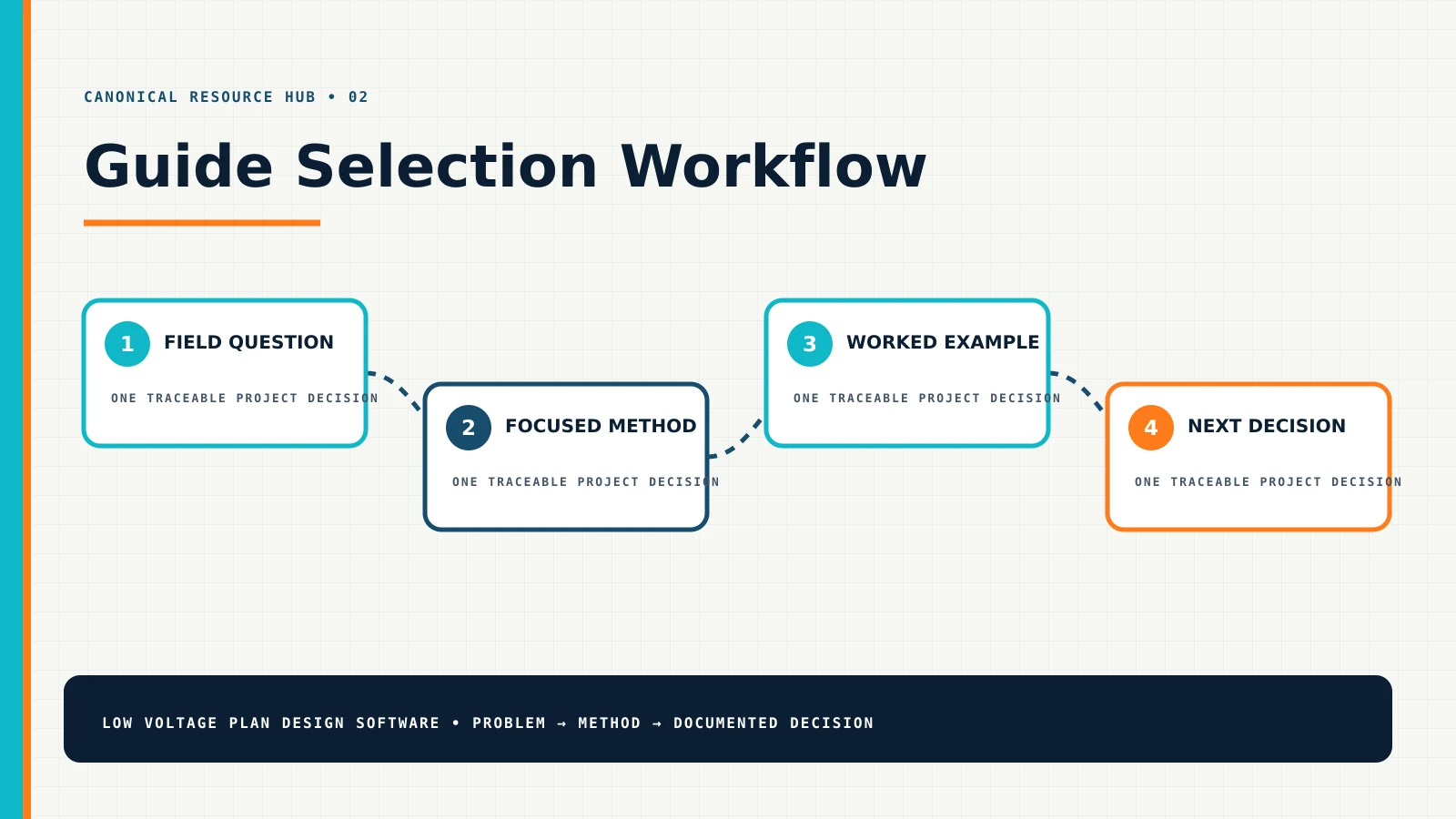
Select the card that sounds closest to the work in front of you. Each route begins with a focused guide and then points to the adjacent document most contractors need next.
Unreliable baseline
The site notes are not ready to become a drawing
Build a controlled field record from measurements, photographs, room and opening IDs, existing conditions, inaccessible areas, assumptions, and decision owners.
Drawing structure
The floor plan is carrying too much information
Separate location, topology, rack order, signal flow, and repeated attributes into cross-referenced documents that remain readable.
Shared routes
Cable lines are cluttering the plan
Create named pathway segments, show transitions and difficult conditions, and connect shared routes to cable schedules and estimating assumptions.
Camera purpose
Camera locations look arbitrary
Define scene purpose, mounting conditions, field of view, lighting, identification needs, network resources, recording, and test evidence.
Camera performance
Coverage cones do not prove useful video
Relate scene width, distance, lens, resolution, pixel density, motion, light, compression, and mounting limitations to the stated objective.
Camera infrastructure
The network diagram is missing system dependencies
Trace cameras through PoE ports, switches, VLANs, uplinks, NVR, storage, UPS, remote access, and cybersecurity ownership.
Controlled doors
Access-control symbols do not explain the opening
Tie each opening ID to reader, credential, locking, request-to-exit, door position, egress, power, controller, network, and hardware responsibilities.
Rack organization
The telecom room cannot be estimated or serviced
Coordinate rack units, patch panels, switches, cable management, NVRs, controllers, UPS, power, airflow, grounding, labels, and growth.
Cable identity
Outlets, cables, ports, and tests do not match
Use one administration chain from outlet through cable and patch-panel port to switch assignment and test record.
Wireless planning
AP symbols are placed without network context
Connect serving-area intent to AP locations, RF assumptions, cable IDs, PoE ports, switch capacity, VLANs, uplinks, and validation.
AV connectivity
Source-to-destination relationships are unclear
Trace signal type, transport, switching, DSP, amplification, control, network dependencies, endpoints, cable IDs, and commissioning evidence.
Commercial scope
The proposal quantity does not match the plan
Reconcile device IDs, accessories, network and storage resources, labor, allowances, exclusions, options, and customer-facing scope.
Follow the project instead of reading guides at random
| Project stage | Question to answer | Primary output | Recommended resource |
|---|---|---|---|
| Discovery | What outcome, risk, workflow, or user need starts the project? | Approved brief and open-question list | Choose a discipline |
| Site survey | Which existing conditions are verified, inaccessible, or assumed? | Measured baseline, photo index, condition log | Site survey to floor plan |
| Location design | Where does each device belong and what purpose does it serve? | Floor plan with stable IDs and design intent | Floor-plan design workflow |
| System relationships | How do devices connect to rooms, racks, panels, networks, and endpoints? | Riser, network map, signal flow, or controller diagram | Plan versus riser |
| Schedules and takeoff | Can every quantity and attribute be traced to its source? | Device, cable, door, rack, port, and BOM schedules | Schedules and estimating |
| Proposal | What is included, excluded, optional, assumed, and customer-provided? | Customer-readable scope tied to a design revision | Proposal design workflow |
| Handoff and closeout | What changed, what was accepted, and what was actually installed? | Approved revision, change record, tests, training, record set | Sales and project handoff |
Example: from a camera concern to an auditable proposal
- Record the customer objective.“Identify people entering after hours” is more useful than “add cameras.”
- Survey the scene.Document entrance width, approach direction, mounting options, light, obstructions, network location, cable route, and privacy boundaries.
- Place and schedule the camera.Assign CAM-01, state its purpose, show coverage intent, and record mounting and optical assumptions.
- Map infrastructure.Connect CAM-01 to cable ID, PoE port, switch, VLAN, NVR channel, storage basis, UPS, and remote-access responsibility.
- Reconcile commercial scope.Add mount, junction box, cable, connectors, pathway, port, license, storage, labor, lift, testing, training, and exclusions.
- Issue and control the revision.Make the proposal reference the approved plan and keep changes attached to the same device identity.
The connected reading path is camera placement → field-of-view review → network diagram → BOM and proposal.
Use the library differently depending on your role
Owner
Standardize the company method
Use the discipline hubs and workflow pages to define what every survey, drawing, estimate, proposal, and closeout package should contain.
Designer / estimator
Control inputs before counting
Start with the site survey, floor-plan structure, schedules, and transparent tool methods. Keep verified quantities separate from allowances.
Sales
Explain scope without losing technical truth
Use examples and direct-answer sections to translate design decisions, exclusions, options, and customer responsibilities into readable proposal language.
Project manager
Protect the approved revision
Follow IDs and assumptions from accepted proposal to submittal, procurement, installation, change control, commissioning, and closeout.
Field technician
Find the detail needed for the next action
Use schedules, diagrams, checklists, and definitions to locate equipment, confirm relationships, label work, record deviations, and return reliable closeout information.
Authoritative reference starting points
Use these sources to verify current terminology, practices, product context, and standards direction. Confirm the edition, jurisdiction, manufacturer requirements, and project applicability before relying on any external reference.
- TIA standards announcements — current telecommunications standards activity
- AVIXA AV glossary — audiovisual terminology and industry context
- Cisco campus LAN and WLAN design guide — network, wireless, switching, and PoE design context